Are you familiar with Little Wars? In 1913, novelist H. G. Wells published it, the first set of rules for miniatures wargaming available to the public. Toy soldiers careen across carpeted (or cork-floored, in the original conception, but I don’t have a cork-floored playroom) countryside, under fire from spring-loaded toy cannon as they charge home for glory.
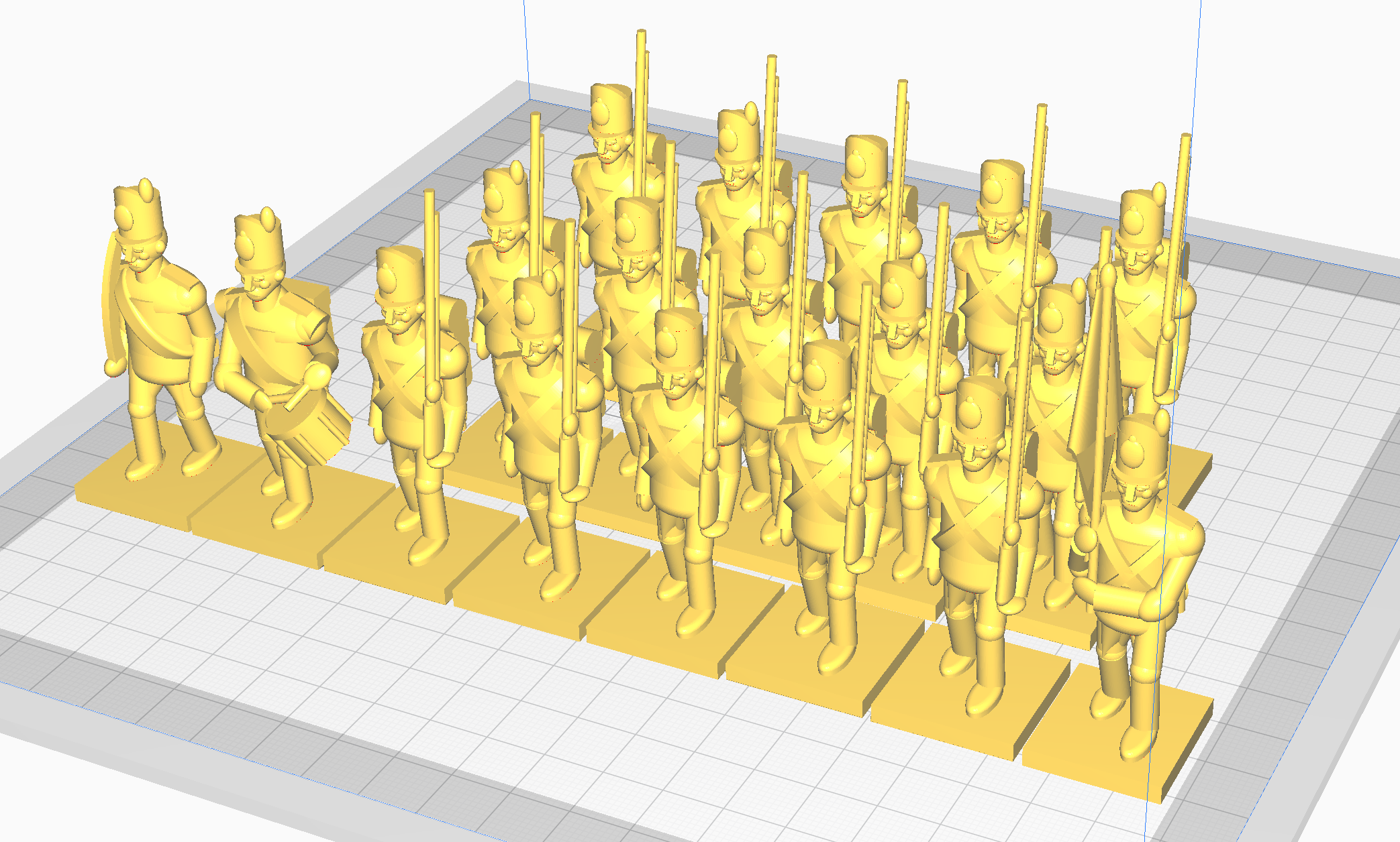
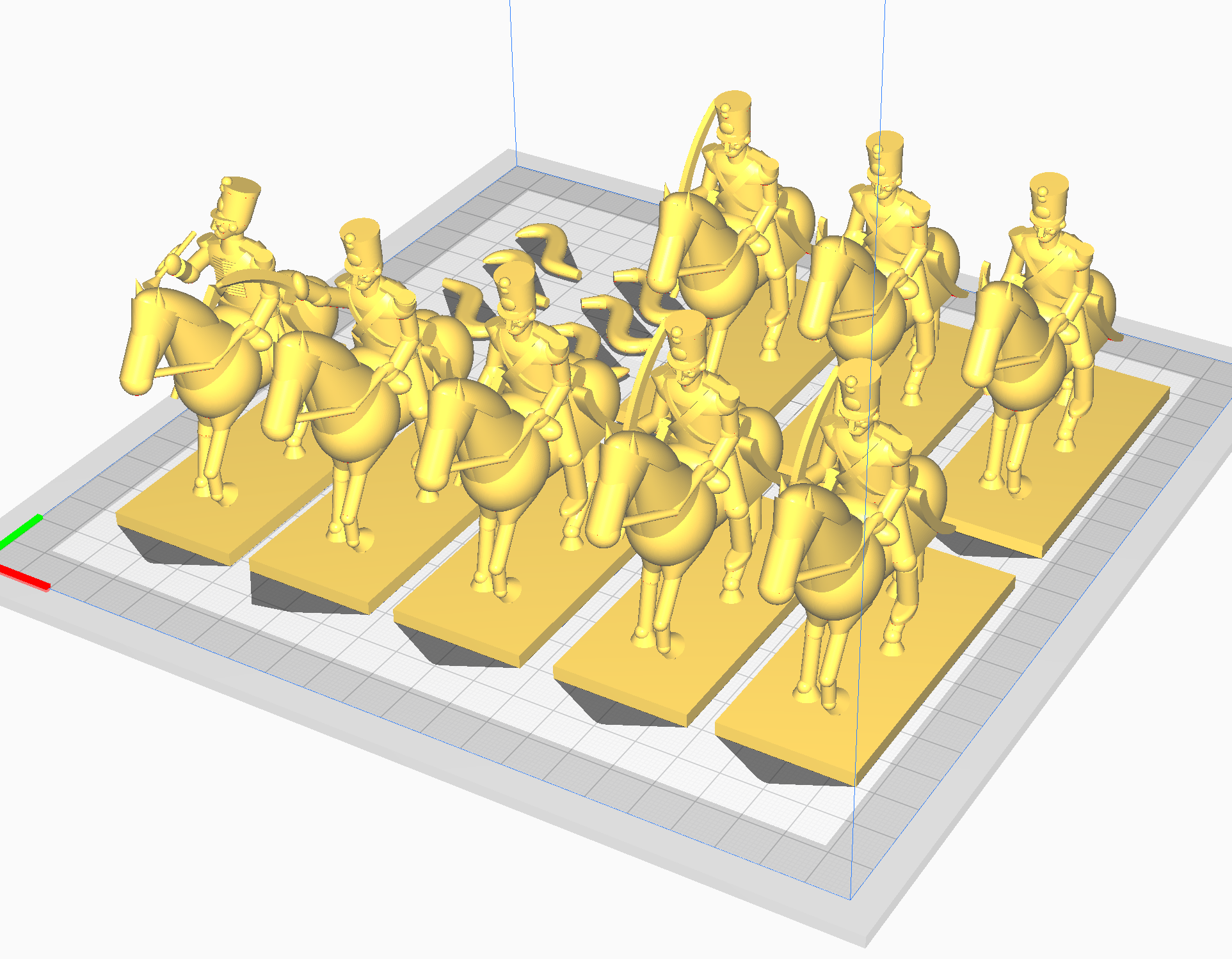
“Sounds great! Where do I start?” I said. Well, toy soldiers aren’t too hard to find, but I decided that I can print better ones, or perhaps eventually cast them in resin from silicone molds around 3D-printed masters.
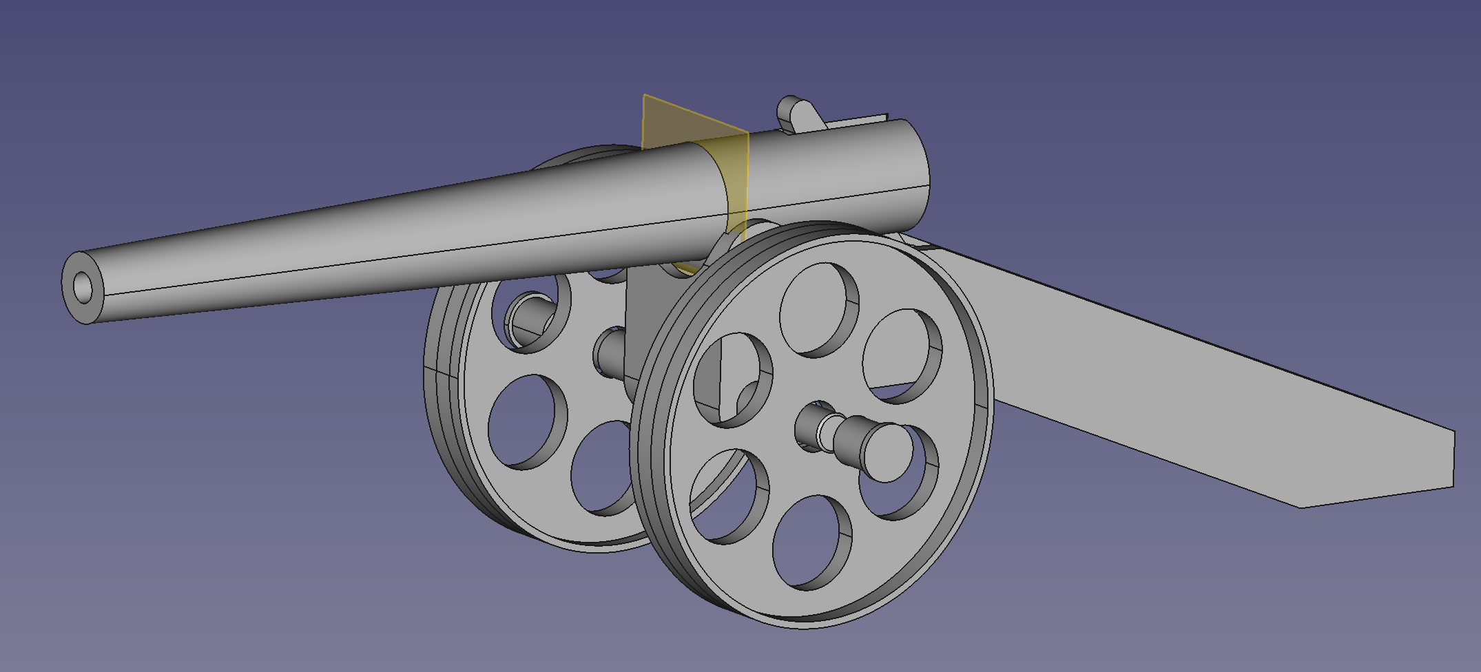
The mighty artillery, however, is the sticking point. Nobody makes toy cannons of the right power anymore, and the early-20th-century originals from Britains Ltd. run about $50 a piece. Not exactly cheap, and especially not when a Little Wars game of moderate size might call for six or ten guns. I have in my possession, however, a 3D printer and a copy of FreeCAD, and armed with these tools, I set about fixing this availability problem, with the help of my Thanksgiving vacation.
That holiday at my in-laws being a pretty sedate affair—an awful lot of movies1 and television—I had ample time to Google my way to a minimum understanding of how to CAD, or at least how to use one of several alternative (or redundant, uncharitably) workflows in FreeCAD. Et voila!
But this is an engineering project, and more to the point, it’s pretty much the first mechanical thing I’ve ever designed. It’s also the first part I’ve 3D-printed that requires high dimensional accuracy and a knowledge of my printer’s capabilities for parts with fine clearances and tolerances.
So, much like my software projects, this one ended up taking a few revisions. The first one ended a bit early, thanks to a slight printer maladjustment. Ooops. Happily, it printed enough of the barrel before the attack of the spaghetti monster so that I could get some testing in. Reader, do not be deceived. This small success sits atop a litany of failures. My notes indicate no fewer than 10 changes to the drawings before the second revision kicked off.
There were three classes of problem in the first revision: dimensional errors, tolerance issues, and firing geometry. The dimensional errors were the easiest to resolve. Everything lined up, but the barrel was too small for a sufficiently powerful projectile, and the wheel hubs were printed to the exact same inner diameter as the axle shaft they were supposed to snap on over. No good.
The tolerance errors stemmed from my traditional forgetfulness about how 3D printers tend to make holes slightly smaller than they’re supposed to be, in both horizontal and vertical surfaces2. I ended up adjusting the drawings to solve that issue, rather than using printer settings, since the printer settings only apply to holes in horizontal surfaces, and it would have been the height of confusion to have adjustments in the CAD files for only one of the two classes of hole.
The firing geometry issues came down to an incomplete understanding of how the hammer would interact with the leaf spring, and how it would swing forward. Let’s zoom in on the evolution of the hammers. We’re concerned with the leftmost one at this point.
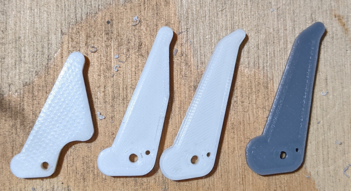
There are two things wrong here, one of which can be sussed out from the photo, and one of which requires more context than I’ve given you. Take a second and try to figure it out.
Done? Okay.
So, item one, the one that doesn’t require the rest of the model to see. The body of the hammer is forward of the pivot, which means that the curve it describes when the hammer moves forward interacts with the projectile far too early. Item two, the one for which you need the context: the bottom of the hammer doesn’t actually extend below the centering braces in the carriage, so when it’s in the up position, it’s not under spring tension—it’s slowing down by the time it hits the projectile.
Still, even with those problems, and the fact that the carriage didn’t sufficiently center either the barrel or the hammer, the initial tests were promising enough to keep me chipping away at the project.
Revision 2 featured a much straighter hammer design, as you can see in the picture a few paragraphs ago. The design intention with the first two revisions was a hammer that would strike the breech flat, spreading the impact forces, rather than concentrating them. This was a goal motivated by a misunderstanding of the strength of 3D-printed parts. Both the hammer and the barrel have proven to be more than strong enough to handle the stresses involved.
Revision 2 also saw the addition of a firing pin hole, which was intended to hold the hammer against spring tension and allow a pull-to-fire mechanism. Ultimately, it never quite worked. The placement of the firing pin holes held the hammer too far back; on pulling out the firing pin, it would simply stay in place.
The third revision introduced an alternate solution: a hammer with a forward-swept tip, so that when it’s resting all the way back against the spring, in fully-cocked position, there’s a place to flip it up with a fingernail. This proved to be remarkably effective, and relatively easy to do without upsetting the aim of the gun to boot, provided the hammer is near the tipping point.
That final observation brought about the fourth revision of the hammer. It has a flat spot between the radii of the rear nub, creating a half-cock position. The hammer can be pulled all the way back to load (if needed), moved forward to the half-cock position, then easily released with a fingertip. The fourth revision also had a few geometry changes: the angle between the base of the hammer and the front surface is more acute, which means its rest position is slightly more vertical. This helps with firing at high elevations.
The carriage developed more slowly. The first thing to change from the drawings above was the profile of the carriage. Originally flat-sided, I changed it to taper from wider at the wheels to narrower at the end of the trail, so that it would fit a 1/2″-wide length of spring steel without any side-to-side play.
Next up is the least obvious change: the clearance between the trigger centering braces on the inside of the carriage and the trigger. This keeps on shrinking. It started at half a millimeter, and has gone down to a tenth of a millimeter over the last few revisions. It could probably stand to be even smaller. It turns out that this printer (3D printers generally?) are capable of very good dimensional accuracy on these sorts of parts.
Finally, the most obvious change: the addition of the elevation screw housing. It’s one of the simpler parts of the design, but I’m inordinately proud of this one on the grounds that it worked as designed on the first print. I did have to go back and enlarge the screw hole slightly, and it works much better now that I’ve started tapping the hole with a tap, as opposed to the machine screw itself.
Which brings us to the final product.
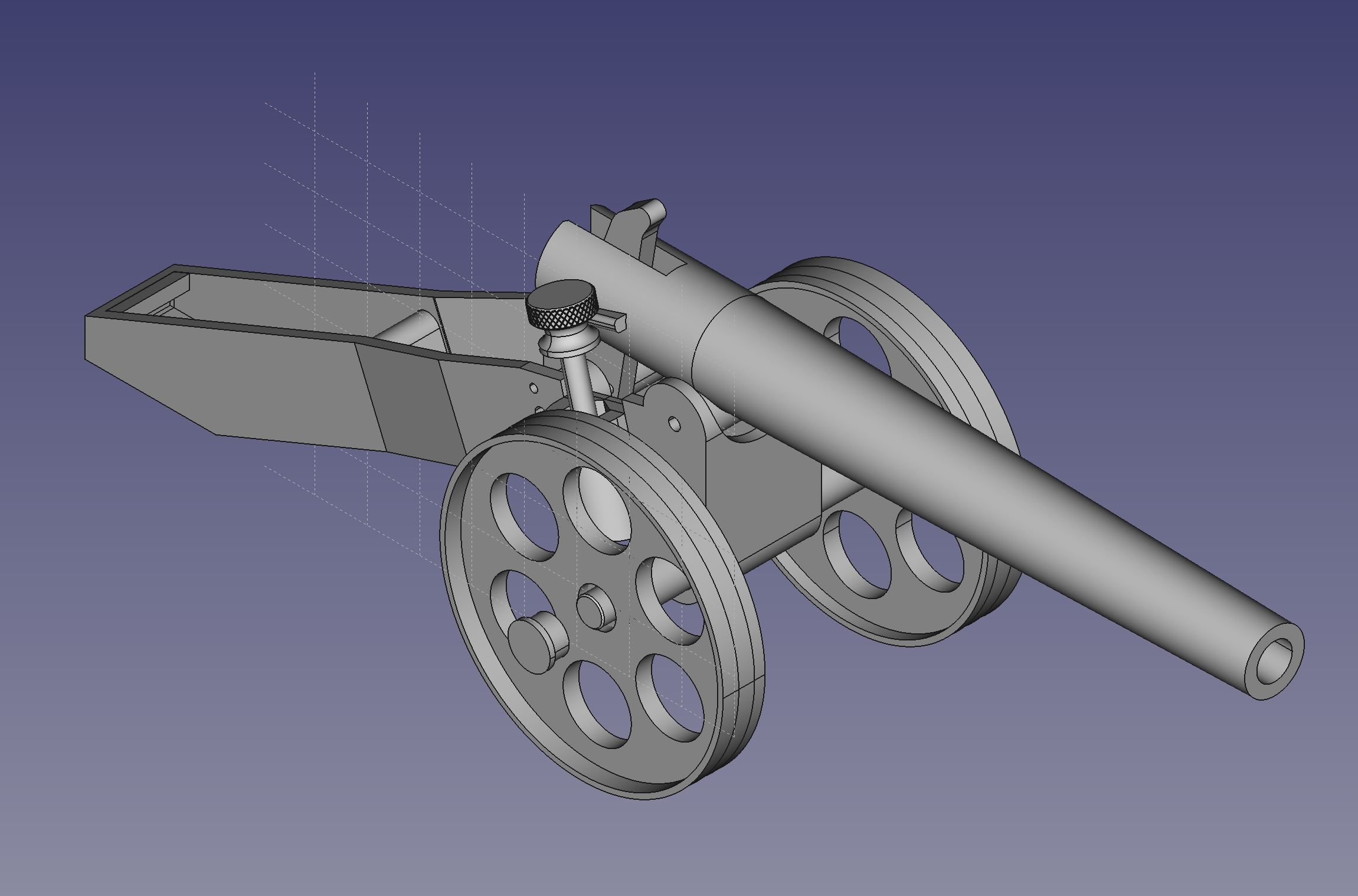
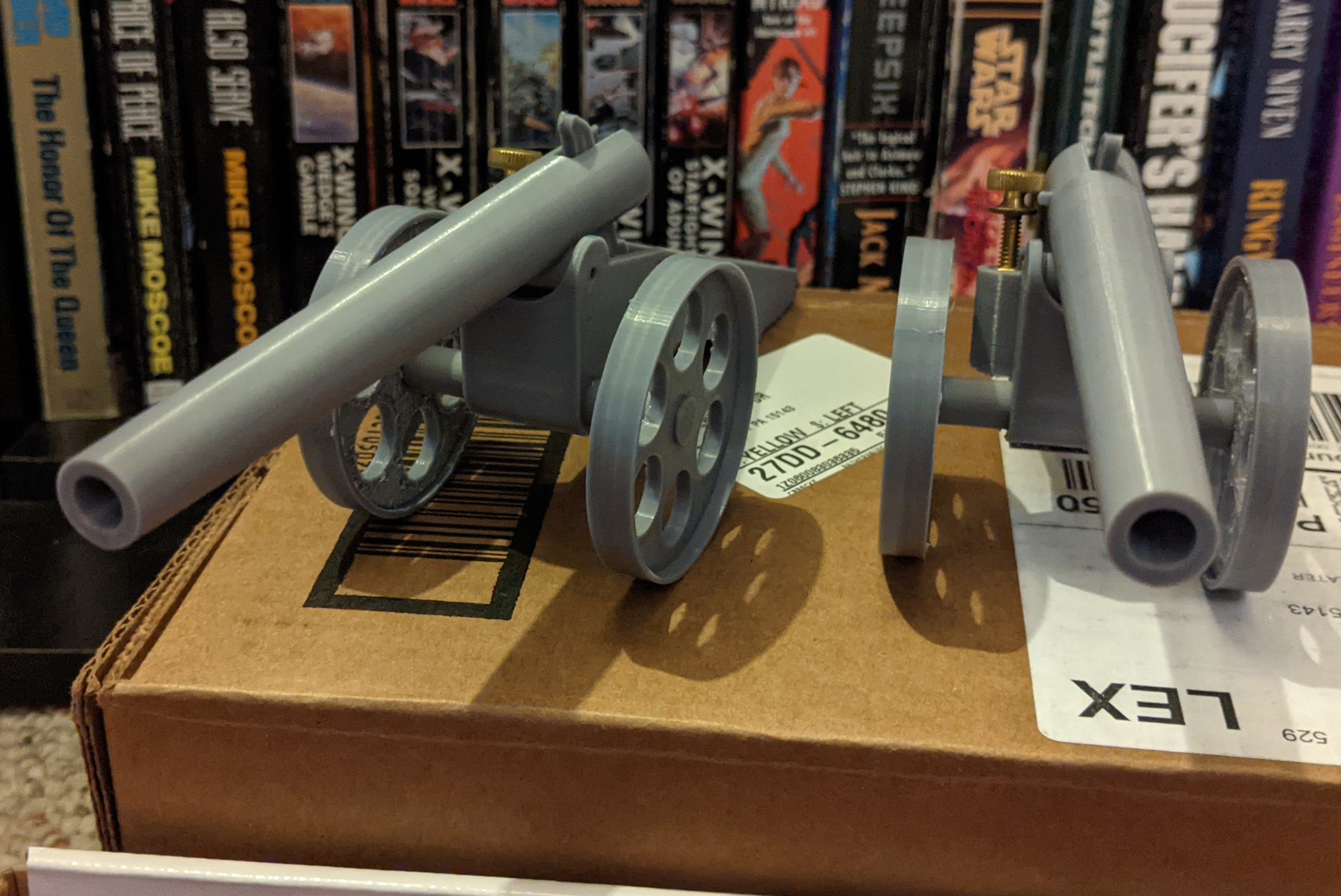
Not bad! It works like you’d expect. Pull the hammer back, load a projectile, flip the hammer forward, and it spits a projectile across the room. It doesn’t quite have the range H. G. Wells reported in Little Wars (able to hit a toy soldier nine times out of ten at nine yards; history does not relate if he was exaggerating), but it will easily reach out to nine yards at maximum elevation. My chronograph said an earlier revision was reaching 30 feet per second, and this one is moderately peppier (although the chrono wasn’t picking up the white plastic shells today, so I can’t tell you how much peppier). That’s enough zip to easily knock over the toy soldiers I’m printing for the purpose and (handily) not quite enough to blast parts off of them.
Which brings you to about the present day. I’m hoping to play a game with my brother, and perhaps a few with parvusimperator in the dark of winter, before outdoors pursuits rob us of the will to play at indoorsy ones. Keep an eye out.
- Ford vs. Ferrari was a highlight, although like almost all biographical movies it’s a bit of a bummer in the end. ↩
- Or at least, this has been my experience. Hole shrinkage in flat surfaces is well-characterized; hole shrinkage in vertical ones less so. I suspect the latter is an artifact of the stair-step nature of round features in vertical surfaces; when you’re making a hole for a 2mm pin, .1mm steps may make a difference. ↩
Pingback: Fishbreath Plays: Little Wars | The Soapbox
I’ve also been looking to 3D print artillery for little wars. What type of spring did you use and where did you get it? One issue I am also considering is that the inside of a 3D printed barrel is not smooth so I’ve thought of lining it with a brass or aluminum tube.
I bought a 1/2″-wide strip of 1075 spring steel from McMaster-Carr and cut it to length. (I don’t know what the situation is for buy-anything industrial suppliers outside the US.) 0.032″ thickness works well in the 4.7″ design, but is pushing the bounds of what the plastic can handle in my 12lb Whitworth. I think 0.020″ or 0.025″ would probably work better in that design. Weaker springs might be better for me in general, since I’m playing with plastic soldiers—powerful cannon tend to send a whole group of men flying at once, which is not entirely desirable.
My barrels are bored 0.75mm oversize (6.75mm for a 6mm plastic dart). That’s sufficient to work without lining, although the shells sometimes tumble during flight. I’m curious how lined barrels would do, though! If you go that way, feel free to leave an update.